Question
How do I set up the Blue Phantom 2 for taking scans?
Answer
Set up the Electrical Lift Table
Step 1
Place the BP2 on the Electrical Lift Table (Table).
Step 2
Move the Table under the machine (Gantry at 0°).
Step 3
Switch on the light field. Open the field as wide as possible.
Step 4
Move the Table so that the light field crosshairs approximately aligned to that of the bottom of the BP2.

Step 5
Lock the Table parking brakes a.
Step 6
Use the lateral adjustment handles (b) for fine adjusting the position. Ensure that the light field crosshairs and the crosshairs on the bottom of the BP2 are superimposed.
Step 7
Place the spirit level in the phantom tank and turn the vertical adjust hand wheels (c) to adjust the phantoms to a perfect horizontal position.

Fill the BP2 Water Reservoir
Step 1
Push the quick coupling d of the Water Reservoir hose to the counterpart in the phantom e.
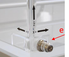
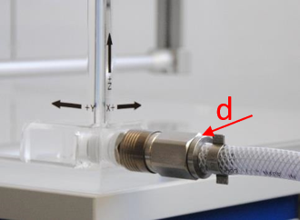
Step 2
Press the Fill button on the Water Reservoir hand control.
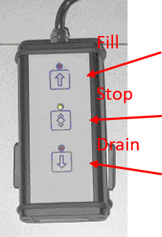
Adjust SSD
- Switch on the light field and the distance indicator, and open up the field.
- Adjust the height with the Table hand control until the SSD is reached.
Set up detectors and connect the devices
Step 1
Place the PC in the control room, and the CCU in the treatment room (min. 3 m distance to the primary beam).
Step 2
Connect the CCU with the PC via an Ethernet switch or the local network with network cables.
Step 3
Set up CC13 chambers (See Sec. 6.2.5,Blue Phantom2 User’s Guide for other detectors)
To set up the Field detector
Step 1
Insert the holder’s dovetail groove into the counterpart of the X-axis slider until a noticeable snap sound occurs. Fasten the screw f carefully.
Step 2
Insert the chamber into the alignment cap (cap) as far as possible until the black ring.
Step 3
Place the front part of the cable into the holder and then move the cable backwards until the cap touches the holder. Fasten the screw g.

To Setup the Reference detector
Step 1
Unscrew the screw h and then insert the reference detector into the reference holder tube. Fasten h again to lock the detector.
Step 2
Clamp the reference detector holder on one corner of the phantom and fasten the screw i.
Step 3
Insert the reference detector cable into the cable clamps.


Step 4
Connect the reference detector to the CCU Field Sensor input through an extension cable.
Step 5
Place the reference detector at one corner of the measurement field just enough to cover the complete active volume of the detector.
Fine levelling the BP2 3D servo frame to the water surface
Step 1
Switch on the CCU.
Step 2
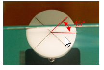
Turn the cap so that the front crossline of the cap is 45° to the water surface.
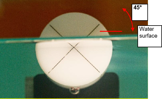
Step 3
Use the CCU hand control to move the detector to the water surface and one corner of the BP2.
Step 4
Look at the cap from below the water surface. The cross point is aligned to the water surface when the lines in water and their images form a perfect cross (see above Step 2).
Step 5
If the first corner is not at water surface, use the hand control to move the detector to the water surface.
Step 6
Use the CCU hand control to move the detector horizontally to the next corner.
Step 7
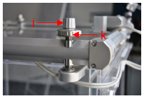
If the detector is not at the water surface, loosen the locking screw j, (Step 9) and adjust the leveling screw k of this corner. Fasten the locking screw again when finished.
Step 8
Repeat the previous three steps for the rest of the two corners.
Step 9
Since leveling one corner may slightly affect other corners, move the detector to each corner to check the level. Adjust if necessary.
Defining water surface and isocenter
Step 1
Turn the cap 45° so that one line l on the front of the cap is aligned to the water surface and the cross marker m is at the top position.
Step 2
With the hand control, move the detector to the CAX until the side cross marker m matches the cross hair of the light field.
Press  and then
  to save the water surface.
Press  and then
  to save the iso-center