Question
How do I perform precision alignment and levelling with Blue Phantom 2?
Answer
ESTIMATED TIME (30-45 min)
On all Blue Phantom 3D tanks there are two horizontal alignments relative to water surface, three perpendicular angles, and four vertical alignments. Before beginning the alignment, it is recommended to put all of the components in a “neutral position”. A neutral position will create a solid foundation for making all of the adjustments and insure all mechanical adjustments are capable of moving equally in either direction.
NEUTRAL POSITION PROCEDURE
1. LEVELING TABLE ADJUSTMENT
Position all adjustment screws 25mm or 7 full turns from full down position.
2. BP2 FRAME ASSEMBLY
Position all four fine leveling screws approximately 6mm from bottom of base.
3. BLUE PHANTOM TANK
Before placing water in the tank, rotate the tank where the sensors are on the side of the table with the two leveling screws.
Loosen the four screws locking the Z rails and leave screws with minimum torque.
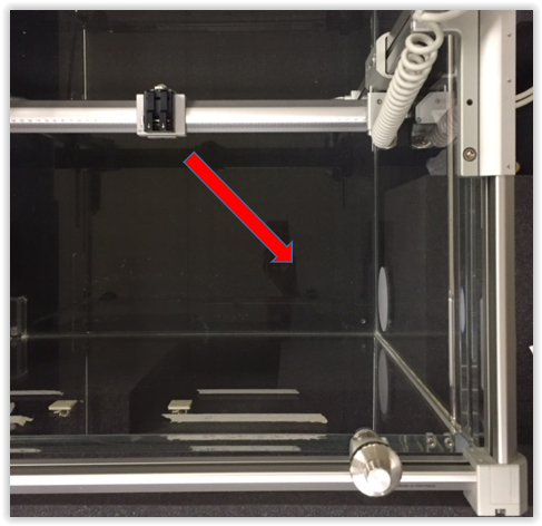
FOUR SCREWS, TWO ON EACH SIDE
A level can be used on the top of the tank body to perform a course level adjustment. Using a level, adjust the side with the two table leveling screws first, then the single screw side. The Field Reference Targets on the sides of the tank are good references to fill an adequate amount of water. Although not consistently reliable enough to use for leveling the tank, they can be used as a reference. Lift tables can settle during the procedure and this reference can be used to check the level / balance during the procedures.
PERFORMING MECHANICAL ALIGNMENT
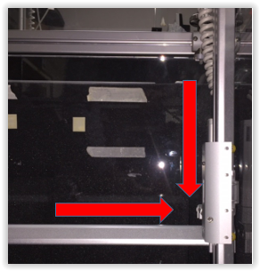
1. RIGHT Y-RAIL PARALLEL POSITION
Place the target in the chamber holder and position the target center, at water surface, in the back right corner of the tank. This is a reference position only. Use the Z-axis control to position, do not adjust the fine leveling screw.
TARGET AT WATER SURFACE
Move the Y-axis to the opposite end of the tank and adjust the position of the target at water surface using the fine adjustment screw. The purpose of this adjustment is to position the right Y-rail to be parallel with the water. DO NOT move the table leveling screws or the fine adjustment screws of this side for the remainder of the procedures.
(FIXED FRAME MODELS W/O FINE LEVELING CAPABILITY: use the two table leveling screws for this procedure). Position the target in the center of the tank to establish a reference and move to either end to adjust.
2. RIGHT SIDE Y TO Z RAIL DIMENSION, Z RAIL CROSSLINE VERTICAL POSITION
Y TO Z PERPENDICULAR
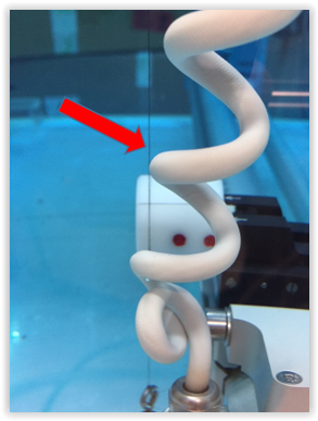
Position the Y rail carriages at or near center tank position with the Z rail carriage and X rail at the top of the Z rail. Align the plumb line with the side of the target and lower the Z rail carriage to check the vertical alignment of the right Z rail in the crossline dimension.
PLUMB LINE ON TARGET
If adjustment is required loosen the two lock screws on the Y carriage, adjust with set screw and lock screws after adjustment.
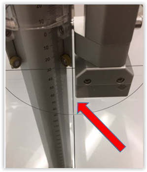
3. Z INLINE VERTICAL POSITION
Place the X rail assembly at the top of the Z rail and the Y rail where the alignment cap close to the tank front wall. Position a plumb line on the target and run the X rail assembly to the bottom of the Z axis.
If the plumb line is left of the target center the tilt of the Z rails are counterclockwise (\\). If the line is to the right of center the Z rails are clockwise (//) from vertical. If the target is at the center for the full travel of the Z the Z is perfectly aligned in the inline vertical position.
A. PLUMB LINE LEFT OF TARGET: The Y rail on the left can be raised by using the left fine leveling screw. (FIXED FRAME MODELS use the single left table leveling wheel)
ALL MODELS: If the line is >2mm left of center use the table leveling screw by rotating the wheel up to 1 full turn. Use the fine leveling screw to raise the Y rail and close the gap. This procedure can change the original position of the reference point at the top of the Z rail. Repeat this procedure until the Z rail is perfectly vertical.
B. PLUMB LINE RIGHT OF TARGET: The Y rail on the left can be lowered by using the left fine leveling screw. (FIXED FRAME MODELS use the single left table leveling wheel)
ALL MODELS: If the line is >2mm right of center use the table leveling screw by rotating the wheel down to 1 full turn. Use the fine leveling screw to lower the Y rail and close the gap. This procedure can change the original position of the reference point at the top of the Z rail. Repeat this procedure until the Z rail is perfectly vertical.
NOTE: FROM THIS POINT FORWARD DO NOT TOUCH TABLE LEVELING SCREWS.
D. LEFT Y RAIL PARALLEL POSITION
The target should be at water surface, in the close right corner, at the completion of step 3.
Move the target to the far left corner of the tank. Using ONLY the far left fine leveling screw adjust the target to water surface.
5. LEFT SIDE Y TO Z RAIL DIMENSION, Z RAIL CROSSLINE VERTICAL POSITION
Repeat Step 2 for the Left Z Rail Crossline Position. Move the Y rail carriages at or near center tank position with the Z rail carriage and X rail at the top of the Z rail. Align the plumb line with the side of the target and lower the Z rail carriage to check the vertical alignment of the Z rail in the crossline dimension. If adjustment is required loosen the two lock screws on the Y carriage, adjust with set screw. Lock screws after adjustment.
6. X TO Z PERPENDICULAR AND Z RAIL INLINE VERTICAL POSITION
X TO Z PERPENDICULAR
ADJUSTING THE X TO Z 90° ANGLE: Move the X carriage to the right and re-establish the target at water level. Move the X carriage from right to left and verify the position of the target at water level. If not at water level loosen the lock screws on the left (motor side) Z rail carriage and use the fine adjustment wheel to raise or lower the target to center of water level. Move the carriage left to right, back to left and verify the target is at water level. Lock the carriage screws.
NOTE: NEVER MAKE THIS ADJUSTMENT ON THE Z SENSOR RAIL. THE LEFT Z RAIL ADJUSTMENT IS SET USING A LASER TO CALIBRATE THE SENSOR.
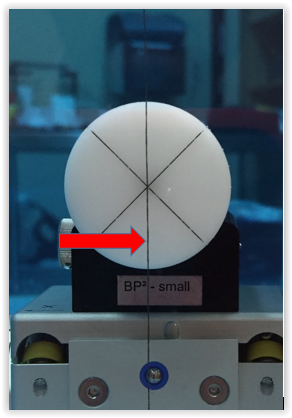
7. Y TO X PERPENDICULAR POSITION
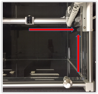
VIEW FROM TOP OF TANK
This is a visual alignment using the Field Reference Target on the side of the tank and the Crossline on the bottom of the tank. If this alignment is off the chamber will be traveling diagonally during scans.
- On the sensor side of the Y axis move the Y axis to the middle of the Field Reference Target.
- Visually align vertical line of Field Reference Target with horizontal Crossline at the bottom of the tank. Use the Y axis control to visually position the rear of the X rail frame in line with the two lines.
VERTICAL & HORIZONAL LINES ALIGNED WITH X
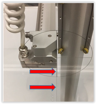
Without moving any of the axis visually compare the other side of the X frame with the same vertical and horizontal lines. In the image shown below the alignment is off approximately 2mm.
Y CARRIAGE IS 2MM RIGHT OF CENTER
This adjustment is very simple with the BP1. The fine adjustment screws are unlocked and there’s sufficient play in the frame mounting to reposition and set this angle. There is no play in the BP2.
To perform this adjustment the X rail carriage will need to have a reference set on one side and repositioned on the other side to perform the alignment. Which side is moved is irrelevant.
However, it is easier to set the reference on the (L) side with the X motor and move the right.
The shaft on both Z rail carriages which the Z rail mounts are variable eccentric shafts.
Once adjusted in proper position these shafts have a lock screw at the end of the shaft.
To perform the adjustment remove the two 5mm bolts holding the X assembly. The X assembly only needs to be slide out sufficiently to access to the shaft for the tool used to rotate it. Once this position is set, tighten the lock screw and the X assembly back into position.
6. FINAL CHECKS
A. Recheck the target remains aligned at water surface in all four corners. If significant changes were made it may be necessary to repeat the entire procedure to obtain perfect alignment.
B. The alignment is complete. Tighten the four screws on the lower Z connector tube.